
Understanding AC Wiring Devices for Any Voltage or Country
AC Wring Devices in the U.S.
In the United States, the voltage ratings for commercial, industrial, and residential power plugs, receptacles, and connector bodies can range from as low as 120VAC, 60HZ to as high as 480VAC, 60HZ. In Figure 1 below, each type of receptacle has a specific NEMA (National Electrical Manufacturers Association) “Device Number” associated with it to describe its electrical configuration.
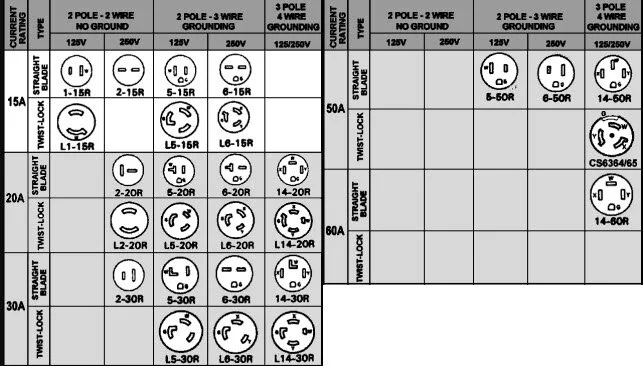
Figure 1 - NEMA Device Numbers in the U.S.
NOTE: In the U.S., All electrical installations are regulated by the application of the NEC (National Electrical Code) to protect people and property from injury, death, or damage. It is not law and the NEC does not participate in electrical installations or inspections. However, the application of the NEC rules certainly can be required as a condition of electrical services rendered. Furthermore, signed contracts containing NEC requirements are legally binding and can be used in litigation. Therefore, it is extremely important to create proper expectations when providing electrical services and maintain all exceptions in-writing.
These plugs, receptacles, and connector bodies are called wiring devices. In order to simplify the task of covering all wiring devices in the world, you must learn “how” these devices work. Then you can easily locate “your” particular wiring device configuration on a “configuration chart” to learn the wiring. NOTE: This is NOT a comprehensive tutorial on wire sizing. This is merely a guide to show you how to select the correct device and make the connections for wiring devices of all voltages around the world. You will see that even though wiring devices around the world look different and may have different safety features, they all work basically the same exact way. And always remember safety first…TURN OFF POWER before performing any electrical work!
To begin to understand how all wiring devices work, we will first look at the most basic devices in the U.S. and then study their similarities to devices around the world. Grab your coffee!
120VAC, 20A Receptacles in the U.S.
TURN OFF POWER before performing any work on any electrical wiring device!
NOTE 1: Use ONLY 12AWG Yellow Romex wire for 20A receptacles because even though 14AWG Hot and Neutral wires are rated at 20A (@75C), the equipment grounding conductor rating is only 15A! REF: NFPA70, NEC 240, 250.4(A)(5), 250.4(B)(4), 250.120, and 310.
NOTE 2: All Neutral conductors ARE current-carrying conductors even though they share a common bus in the load center. The reason is, the Neutral wire is the return from a current-carrying terminal on the load back to the source. However, the neutral wire is often but not always counted as a current carrying conductor when derating conductors, such as when the neutral current is zero (in a balanced system) or if only the neutral (imbalance) current is present. The Ground wire is NEVER connected to any current-carrying terminals on the load. Therefore, the Ground wire is NEVER a current carrying conductor. NEC 310.15(B)(2)(a).
NOTE 3: Some of the installation tips mentioned below do not apply to all wiring devices. To avoid unnecessary repetition, common sense will tell you which of these techniques apply to each wiring device.
For a non-locking straight-blade 120VAC, 20A NEMA 5-20R, duplex receptacle (commonly found in every house in the U.S.), you have 3 wires - Hot (Black), Neutral (White), and Ground (Green). Of the two straight prong openings, the Hot prong opening is the smaller one and the Neutral prong opening is the larger “T-shaped” one (for 20A). The Ground prong opening is the small semi-round opening with a flat side. Cut each wire in the electrical box to about 6 to 8 inches and strip off about 1/2” of insulation. For push-in mounting, strip off only 3/8” of insulation and insert the wires where discussed below. For screw mounting, bend a hook in the end of each wire and install with the wire-end pointing in the clockwise direction to keep the wire around the screws while being tightened. Connect the Hot (Black) wire to either black screw. Connect the White (Neutral) wire to the silver or lighter-color screw directly across. Connect the Green (Ground) wire to the green screw usually at or near the end of the receptacle. Give each wire a tug to make sure they are connected securely and won’t come off. The receptacle should come equipped with a brass strip joining the two Hot screws to ensure both outlets are powered by a single pair of Hot and Neutral wires. If you would like to make one or even two of those outlets separately switched, then just cut or break the brass strip in the middle to separate the two circuits. For switched outlets, two circuits are required but the Hot (switched) wire will travel through a single pole switch. When you finish wiring the outlet, install it in the electrical wall box with the two mounting screws at the top and bottom. Tighten them just enough to keep the device in place but loose enough for the receptacle to line itself up with the outlet cover. The cover screw will help hold the device securely when finished.
240VAC, 20A, 30A, or 50A Receptacles in the U.S.
TURN OFF POWER before performing any work on any electrical wiring device!
For a non-locking straight-blade 240VAC, 20A, 30A, or 50A (that is, NEMA 6-20R, 6-30R, or 6-50R) receptacle, you have 3 wires - Hot 1 (Black), Hot 2 (Red), and Ground (Green). Connect each Hot wire to the brass or darker screws. Connect the remaining Ground wire to the green Ground screw on the device. Give each wire a tug to make sure they are connected securely and won’t come off. Install the receptacle in the box using the mounting screws at the top and bottom. Tighten them just enough to keep the device in place but loose enough for the receptacle to line itself up with the outlet cover. The cover screw will help hold the device securely when finished.
120/240VAC, 20A, 30A, or 50A Receptacles in the U.S.
TURN OFF POWER before performing any work on any electrical wiring device!
For a non-locking straight-blade 120/240VAC, 20A, 30A, or 50A (that is, NEMA 14-20R, 14-30R, or 14-50R) receptacle, you have 4 wires - Hot 1 (Black), Hot 2 (Red), Neutral (White), and Ground (Green). Connect each Hot wire to the brass or darker screws. Connect the Neutral wire to the silver or lighter-color screw. Connect the remaining Ground wire to the green Ground screw on the device. Give each wire a tug to make sure they are connected securely and won’t come off. Install the receptacle in the box using the mounting screws at the top and bottom. Tighten them just enough to keep the device in place but loose enough for the receptacle to line itself up with the outlet cover. The cover screw will help hold the device securely when finished.